A newly installed PLS CADD requires configuring specific settings first.
Preferences
File → Preferences
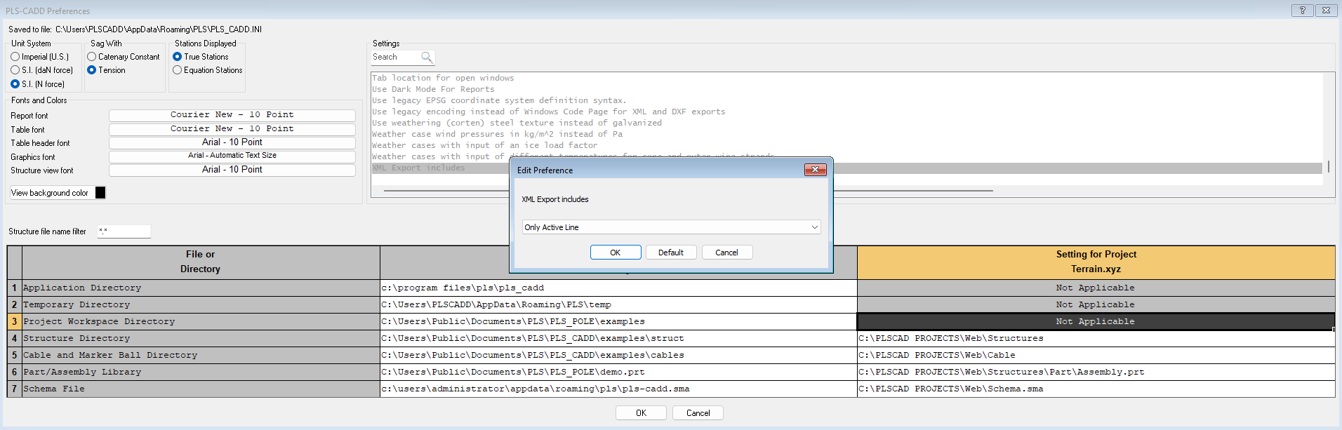
In this window, the user can set up the unit system, cable sagging settings choosing between Catenary Constant (the ratio of horizontal tension to the wire unit load, m) or tension, and other relevant features such as fonts, colors, directories. Other useful settings can be found in the scroll menu.
Other settings can be configured by uploading a schema file (.sma). Refer to this document for more insight on this matter.
After the user's preferences are defined, the next step is to configure the project settings, starting with the coordinate system.
Coordinate System
Terrain → Coordinate System → Define
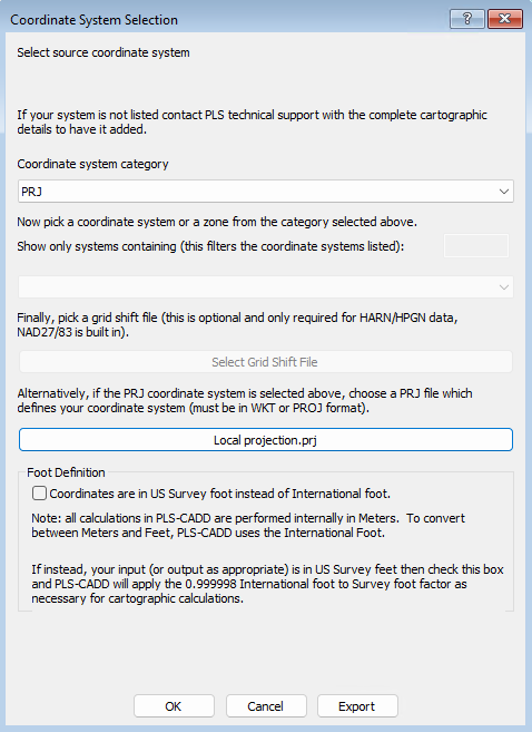
The coordinate system can be configured using either standard coordinate system or local parameters. Where a local coordinate system is required, a .prj file may be requested to automatically configure the project-specific coordinate system parameters.
Fea File
Terrain → Feature Code Data → Edit...
The FEA file aims to define allowable clearances for every type of point and to specify properties for every terrain or obstacle type. Clearance requirements vary based on the voltage of the transmission line.
If you intend to use an existing FEA File, you can upload it using Terrain → Feature Code Data → Load FEA File…
Power Line System provide a comprehensive example of such file.
We recommend developing a single FEA file for each standard to be used consistently across all projects by all members of a company.
Survey Points
There are plenty of options for merging points into PLS CADD. The PLS CADD manual describes thoroughly them all. We will provide a guideline of how to Merge Points from User Defined XYZ file Terrain → Edit → Merge Points from External File → Merge XYZ Points from User Defined XYZ File…
In our example, survey points were generated using a periodic formula.
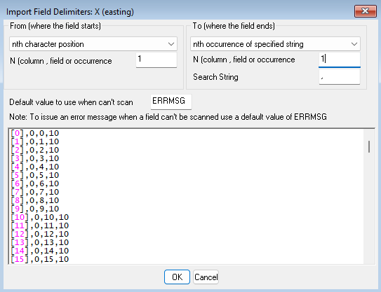
By customizing the import format, we should set the place for X, Y, and Z coordinates and for FEA Code.
If survey points are additionally defined by H (height), the rule is similar.
There are some other useful options for optimizing survey points in PLS CADD:
- To decrease the project size, the point density should be optimized. For that purpose, Terrain → Edit → Deactivate, Delete, or Export Points can be used to filter points by separation distance and feature code.
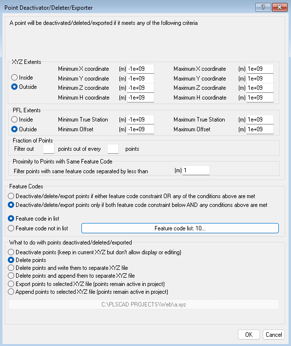
We recommend using these separations for survey points depending on their type:
| Structure base | 5m |
| Ground, vegetation, water | 1m |
| Road, Railway, Pathway, Pipelines | 1m |
| Buildings | 0.5m |
| Line conductors | 0.5m |
| Line insulators | 0.2m |
| Line structures | 0.5m |
| Noise | 1m |
- Terrain → Edit → Delete Duplicate… prevents unintentional duplication when uploading. We advise using this PLS-CADD option every time you upload external survey points.
Almost every project is influenced by survey point input errors. For that reason, it is extremely critical to check the following things before starting modeling:
- FEA complies with the object. You can upload orthophotos if available; if not, use open-source data. For this, use Drafting → Attachments (Raster and Vector) → Attachment Manager… When you have images under your survey points, it’s easy to compare the feature code with the object. If you need to change the feature code (for instance, change the ground level to the road feature code), use this option: Terrain → Edit → Change Feature Code…
- There should be no unclassified objects. If any are reported, check whether some survey points are hidden Terrain → Survey Data Display Option or not active Terrain → Edit → Reactivate Points….
Inactivate points you can check also in the table Feature Code Data Edit.
If all points are shown, then check if the plan symbol is a point and therefore invisible above the image.
If the object is still not covered by survey points, you can refer to those who prepared the survey and ask them to return the missing points.
TIN
With only survey points, some PLS options may not be available. To improve accuracy and functionality, we recommend creating a TIN (Triangulated Irregular Network) model for every project where sufficient survey data are available.
A TIN model connects all ground points into a network of triangles that represent the ground surface. With this model, you can create a point on this surface without manually setting the Z level, as PLS CADD uses the Z level derived from the TIN model.
With Terrain → TIN → Display options, you can show the TIN model and check where your points are unreasonably elevated. You can then delete them. To modify a survey point, first customize snap settings: Left Mouse Click → Change Snap Settings, then choose "Survey Points"; Next, select a point to modify or delete by clicking on it with the left mouse button. This action will prompt several options, including delete.
Alignment
Once the points have been uploaded, we can create an alignment using the survey points. If the points have different FEA codes and there are specific points for line angle structure placement, PLS CADD offers a useful tool which allows us to lay down the alignment using only specific points.
For multiple alignment, it can be challenging to arrange them in a way that allows for seamless stringing sections. PLS follows three rules for stringing:
- Stringing must start and end at a dead-end.
- The stringing direction must follow the alignment directions.
- Stringing must proceed in the ascending order of structure numbers.
However, even if you deviate from some rules and your PLS model is no longer in its initial state, there are tools available to assist you in updating your existing model:
- You can reverse the alignment direction either for the whole project or just for one branch. For the entire project, use Terrain → Alignment → Reverse Alignment. To reverse the alignment for a specific branch, use Terrain → Alignment → Table Edit Alignment.
- You can proceed with stringing cables even with an incorrect stringing direction, and then change the stringing direction in Section → Table → Command To Apply → Reverse Stringing.
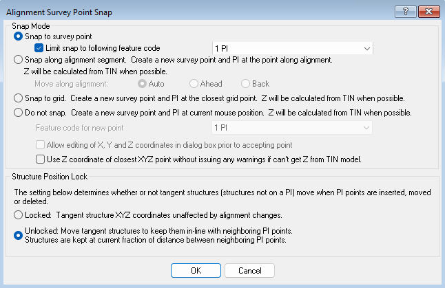
When snapping PI with spotted structures, pay attention to the option: Locked → Unlocked structures locations.To prevent missing intermediate structure locations once you have finished spotting structures, upload the new structure coordinates (taken from the staking table) with specific FEA codes into your model using Terrain → Edit → Merge Points from External File. Having points under structures enables to snap structures to these points using Structures → Automatic Spotting → Snap Station and Height to Feature Code.
Clearance Line
We uploaded points from Excel, created alignment and now we can set up settings for profile and clearance line.
There are two profiles:
The difference between these two profiles lies in Feature Code Data → Edit...
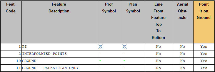
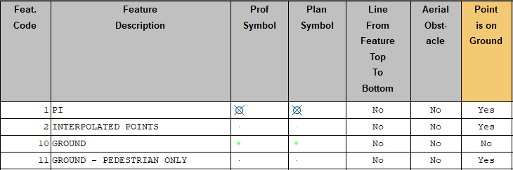
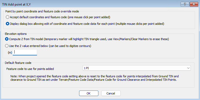
Sometimes manual survey point creation is required, for example when checking clearances to a proposed streetlight or other designed infrastructure. A new survey point can be added using Terrain → TIN → Add Point at X, Y.
The new point may be specified using only the X and Y coordinates, with the Z coordinate automatically adopted from the TIN surface at that location
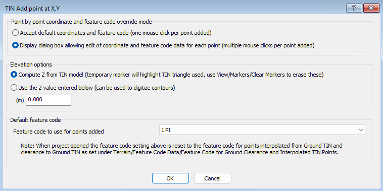
As an example, we modelled a streetlight pole with the specified height above ground.
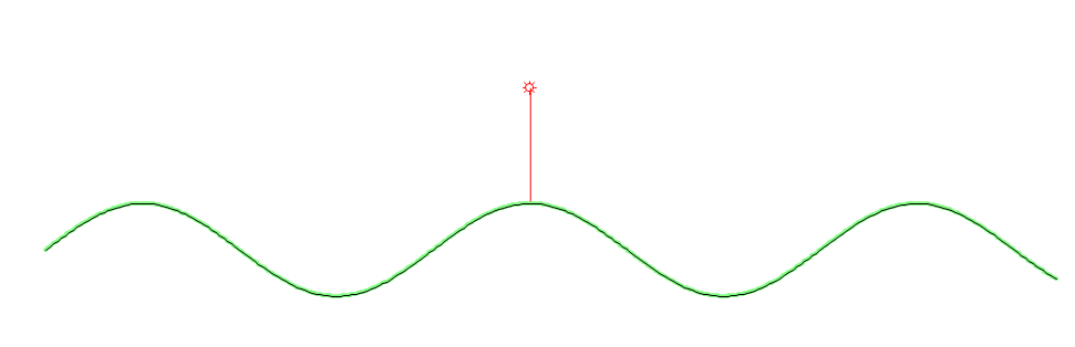
Once the ground line and aerial obstacles have been defined, the settings for visual clearance checks should be configured. These settings control the display of clearance envelopes and assist in verifying compliance with the required clearance criteria.
To establish clearance lines (centerlines) and visual clearance requirements for aerial obstacles (spikes), the Terrain → Clearance Line settings shall be configured.

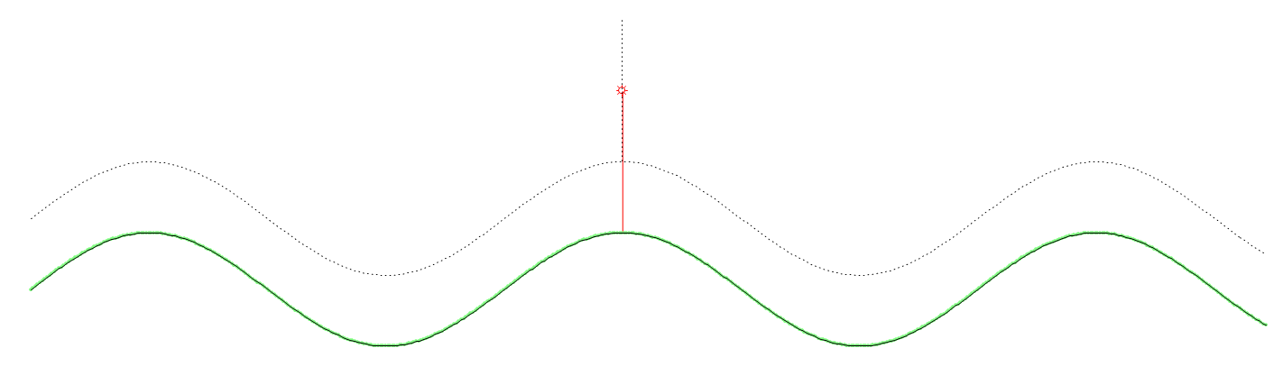
The profile view now displays the clearance line, which reflects the clearance from the Feature Code Data Edit.
Sometimes you can see unexpected vertical lines beyond the ground line as shown below.
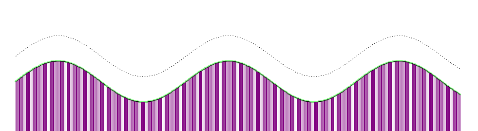
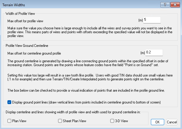
The display of Ground Point Lines can be adjusted through Terrain → Terrain Widths by enabling or disabling the relevant display option as required.